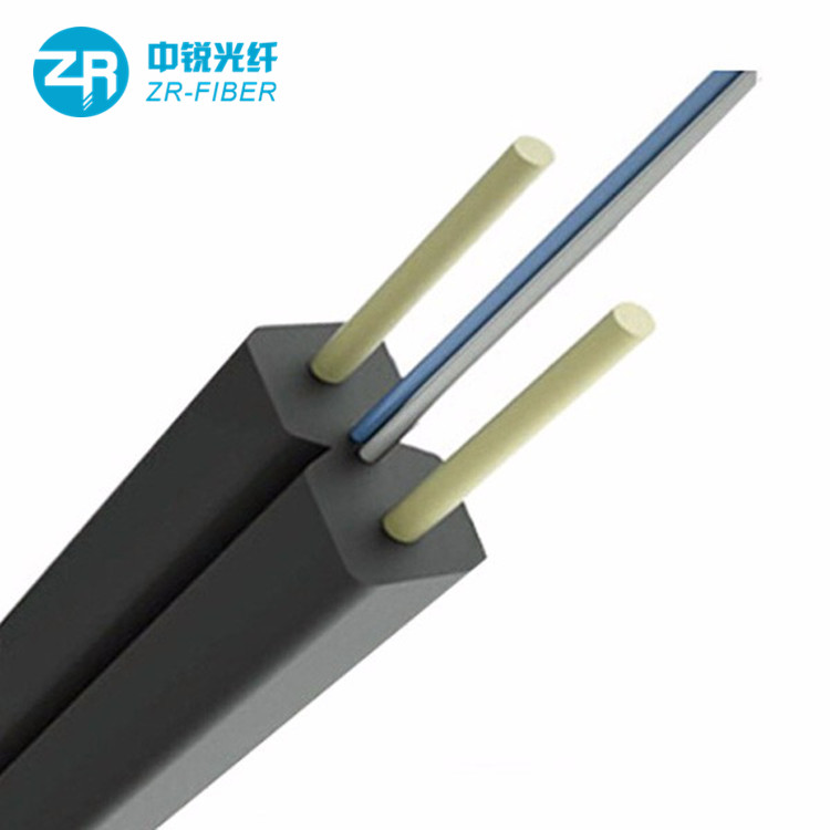
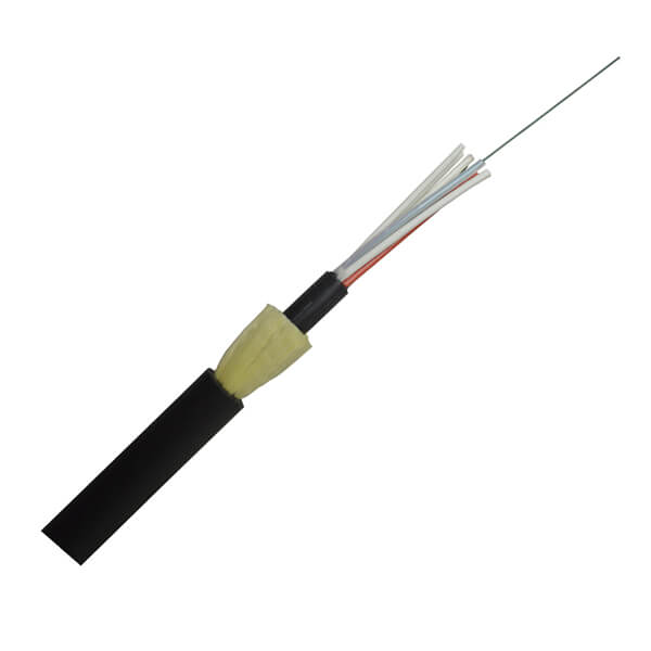
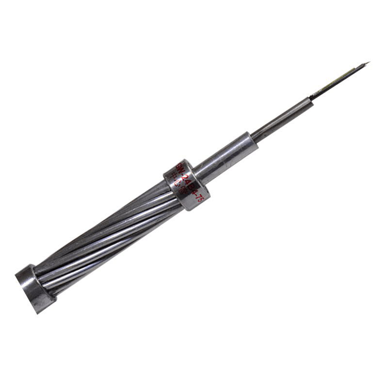
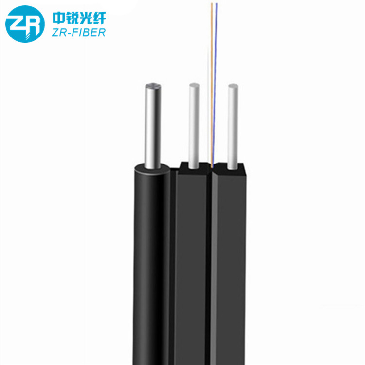
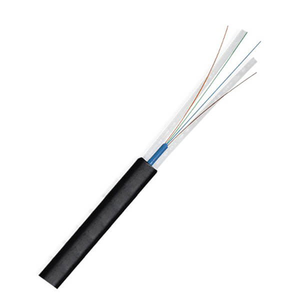
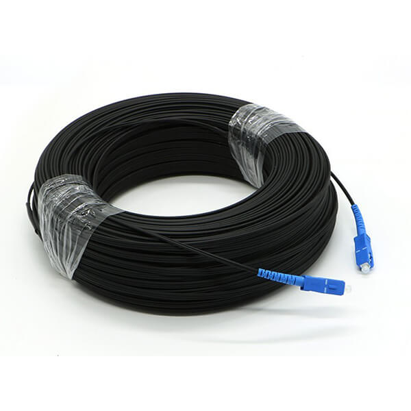
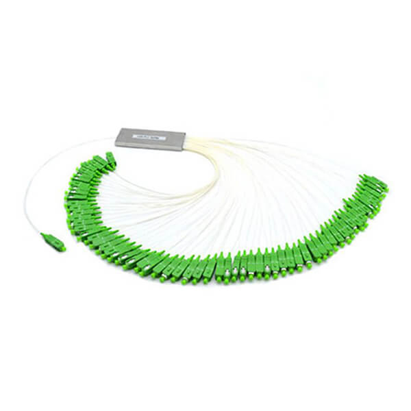
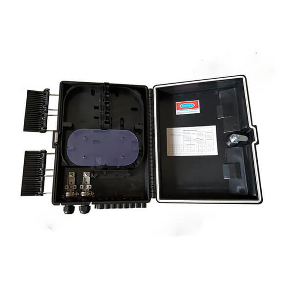

Optical cable is an important component of the entire weak current integrated wiring, and it is also the backbone line for signal transmission. Without optical cable, it is impossible to transmit powerful data services. The importance of optical cable in weak current can be imagined. Today, I will talk about the acceptance standards for optical cable line projects. During construction, we must pay attention to the construction according to the optical cable acceptance standards, which is convenient for later inspection and acceptance, and meets the delivery requirements. The specific acceptance details are as follows.
fiber optic line
1. Computer room side
1. The incoming optical cable should be numbered at the entrance and exit holes and the end of the ODF frame, and the signs should be consistent with the completion data;
2. All incoming/outgoing optical cables and user optical cables should be checked for the reserved length of the optical cables, the placement of the coils, the protection measures and the quality of the ends.
3. The metal components in the incoming/outgoing optical cable should be grounded at the terminal;
4. The entrance and exit holes of incoming optical cables should be blocked with fireproof mud;
5. The optical cable should be laid straight in the channel, without obvious twisting or crossing, and should not overflow the channel. The bend should be moderate, and there should be no dead bend. The part of the optical cable entering and leaving the channel should be bound and listed;
2. Transfer box
1. The assembly of the junction box should be complete with spare parts, the connector row should be undamaged, the terminals should be firm, the braided end optical cables should be fixed in the box, and the number-checking test and insulation test should be carried out, and the paint surface should be intact.
2. The junction box must be grounded separately, the grounding wire should meet the design requirements, and its grounding resistance should not be greater than 10 ohms. Fiber optic cables entering the junction box must be grounded and labeled.
3. The lacquer writing (printing) of the box number and optical cable number of the transfer box should meet the design requirements, and there is a schematic diagram of the routing of the optical cable on the inside of the cover of the transfer box. The fiber jumpers in the transfer box are arranged reasonably and neatly, without joints and without affecting the opening of the module bracket;
4. The installation position of the wall-type junction box should be a solid, firm and safe wall. The distance between the bottom of the junction box and the horizon and the distance between the box and the corner should meet the design requirements (including the indoor junction box); the installation of the overhead junction box should be based on the The design requires the use of H-shaped rods and the addition of a working platform; the selection of the installation position of the floor-to-ceiling transfer box The solid parts of the box body must be firm, safe and reliable, and the installation height and moisture-proof measures should meet the design requirements.
5. Whether the end is standardized (there should be some leftovers to ensure that they can be exchanged at any time, especially the main optical cable part)
6. The entrance and exit of the optical cable under the junction box and the upper end of the optical cable guide pipe must be treated against rodents and ants.
3. Line
Overhead Pole Road:
1. The length of the overhead optical cable random inspection should not be less than 10% of the total length of the optical cable. Along the line, check the distance between the pole and other facilities (including vertical and horizontal), the installation quality of the optical cable and joints, reserve the optical cable, and cross with other lines. Proximity to power line protection.
2. The poles should be spaced from the poles as specified in the design. Under normal circumstances, the pole distance of the urban optical cable line is 35-40m, and the pole distance of the suburban open line is 45-50m. Due to special terrain conditions, the distance should not exceed 65 meters.
3. The erection of the pole should meet the following standards: the pole position of the straight line should be on the center line of the line route, the left and right deviation between the pole center line and the routing center line should not be greater than 50mm, and the pole itself should be vertical up and down. The corner pole should be moved inward at the corner point of the line. The inward displacement value of the cement pole is 100-150mm, and the inward displacement value of the wooden pole is 200-400mm. Due to terrain restrictions or the corner pole installed with braces, it may not be moved inward. After the terminal rod is erected, it should be inclined 100-200 mm to the side of the cable.
4. The cable pulling device should meet the design requirements, the cable should be made of galvanized steel strand, and the method of fixing the cable should be implemented according to the designed material.
5. Insulators should be installed in accordance with the design regulations for the cables close to high-voltage power facilities and lively urban areas. The upper length of the pull wire with the insulator facing upward should be appropriate, but the vertical distance between the insulator and the ground should be more than 2m, and the fixing specifications of the pull wire insulator should meet the design requirements. The cables on the sidewalk should be protected by bamboo tubes or wooden stakes.
6. The pulling wire can be combined with the cement pole using the hoop method; it can be tied with the wooden pole.
7. The horn should be installed according to the design regulations. The height of the word or card of the number pole, the bottom edge of the last word or the number plate of the number plate should be 2.5m from the ground, and the number of the pole number should face the street. The wind in the distribution area of the same computer room should be written in the same way.
8. The minimum horizontal clear distance between the pole road and other facilities should meet the specified standards. That is, the net distance from fire hydrants is 1m, the distance from underground pipelines is 0.5-1m, the distance from sidewalk curbs is 0.5m, the distance from trees in urban areas is 1.25m, the distance from buildings is 2m, and the distance from trees in suburbs is 2m.
9. The minimum vertical clear distance between the pole road and other facilities should meet the specified standards. That is, in the streets of the city, the vertical clear distance from the lowest cable to the ground is 5.5m; in the hutong (lilan), the vertical clear distance is 5m; the vertical clear distance on the highway should be higher than 5.5m; the general dirt road is 4.5m; 0.6m; when crossing the river, the highest mast top is 1m when the lowest cable is away from the highest water level;
10. The minimum vertical clear distance between the pole road and the power facilities shall meet the specified standards. With the power line below 1kv, the minimum vertical clearance distance from the highest cable to the power supply line is 1.25m, the minimum vertical clearance distance for the power line below 1~10kv is 4m, and the minimum vertical clearance distance above 35kv must be more than 5m; and the power supply line is connected to the household line (with insulation layer) The net distance is 0.6m, and the distance from neon lights, iron frames and power transformers is 1.6m.
11. When the crossing of the line and the power line cannot meet the above requirements, a special power insulating sleeve should be used for protection.
12. The distance between the hooks should be 500mm, the allowable deviation is ±30mm, the first hooks on both sides of the pole should be 250mm away from the pole, and the allowable deviation is ±20mm.
13. The optical cable after overhead laying should be straight, without twisting, and without mechanical damage. The optical cable is reserved for a pole bend every 5 poles, and it is reserved between the hooks on both sides of the pole to sag by 250-300mm, and is protected by a plastic tube.
14. Signs must be hung when the line turns and passes, and the content must meet the requirements of the operator Party A.
pipeline:
1. The holes for laying pipeline optical cables should meet the design requirements.
2. The number of random inspections of pipeline optical cables is 10% of the total number of wells. Check the installation quality of optical cables and connecting and decoration, protection measures, the arrangement of reserved optical cables, the blockage of nozzles, and the markings of optical cables and sub-pipes.
3. All direct-buried optical cables should be inspected along the route and the location, specification, quantity, buried depth, orientation and reinforcement and protection measures of the marking stones.
4. Three or more sub-pipes should be applied at a time in cement pipes or plastic pipes with a diameter greater than or equal to 90mm.
5. The sub-pipe shall not be laid across the well, and there shall be no joints in the pipeline, and the pipe hole of the sub-pipe shall be blocked according to the design requirements.
6. The radius of curvature of the laying pipeline optical cable must be greater than 20 times the diameter of the optical cable.
7. When pulling the optical cable manually, it should be relayed in the downhole section by section. When laying around the "8", its inner diameter should not be less than 2m.
8. After laying, the optical cable should be placed against the wall of the manhole, and it should be tied to the shelf with a cable tie, and kept straight, without cross, twist, and obvious scratches and damages.
9. The length of the optical cable joint after laying should be reserved according to the design requirements, and should not be bent within 150mm of the outlet hole.
10. After the laying of the optical cable, a sign should be hung in each well in time, and the content should be filled in according to the standards stipulated by Party A.
11. When the optical cable passes through the termite damage area, protective measures should be taken according to the design requirements.
12. Whether the construction process of the sub-pipe meets the specifications or design requirements; the main contents are: (1) the specification and model of the plastic sub-pipe; (2) the position of the pipe hole occupied; (3) the length and mark of the sub-pipe in the man (hand) well; (4) Sub-pipe laying quality; (5) Installation of sub-pipe plugs and sub-pipe caps;
13. Connection and packaging of optical cable:
1. The model, specification and program of the connecting casing should meet the design requirements.
2.The connection of the fiber optic cable strength core should be clamped and clamped firmly according to the structure of the splice box, and can withstand the same tensile force as the fiber optic cable.
3. The optical fiber splice loss should meet the design requirements.
4. Installation of the splice box: 1) The optical cable at both ends of the hanging overhead optical cable joint should be telescopically bent, and the reserved optical cable at both ends should be placed on the adjacent pole. 2) The pipeline optical cable joint must be installed on the optical cable directly above the manhole On the connector box bracket, the connector optical cable should be close to the manhole wall or manhole shelf, coiled into an "O" ring, and fixed with a cable tie. Note that the radius of curvature of the "O" ring should not be less than 20 times the diameter of the cable.
5. The optical cable splice box must be tied firmly, each branched optical cable must be hung with Party A's identification plate, and the content must meet the requirements.
4. Test
1. Each optical fiber should be tested for the hop fiber line, and the number of tests should be no less than 25% of the number of fiber cores during acceptance.
2. When the backscattered signal curve of the fiber in the relay section is completed, each fiber should be inspected, and the number of sampling tests should not be less than 25% of the number of fiber cores during acceptance.
3. The bandwidth of the multimode fiber and the dispersion of the single mode fiber are determined according to the engineering requirements.
4. To verify the joint loss, the fiber attenuation should be considered according to the test results.
5. Test indicators: Generally, the loss value of a single joint point should not be greater than 0.08dB, and the average loss value of the repeater should be within the range of 0.15 to 0.25 dB/Km.
1) Overhead part standard:
1. Check the direction of the pole path, the position of the pole cable (strut) buried, the pole height and the pole distance, the type of the cable, the position of the optical cable joint, the position of the remaining optical cable, and the total length of the pole road, etc. are consistent with the as-built drawings.
2. There is no cross between the optical cable and the hanging wire, the sag of the steel strand is less than 30 cm, and the distance between the hooks is uniform and 50 cm (plus or minus 2 cm). 3. When the optical cable crosses the pole, there should be left a drip bend, and the bottom of the drip bend is 15-20 cm away from the steel strand; when crossing the special pole, the optical cable should be protected by a hose.
3. Reserve 15 meters (plus or minus 2 meters) on each side of the optical cable joint. The joint and the remaining cable should be bundled, fixed on the pole and marked with a mark. The joint box should be vertically fixed on the pole with the heat shrinkable tube downward. , in case of a pole across the pole, the joint box should be placed on the other side of the road.
4. Every 500 meters of the optical cable or the place where it is needed (a pole in front of the road, lead well/pole, access to the outside of the computer room, etc.) should be left over, and the reserve should not be less than 20 meters; the reserve cable should use 7* 2.2 The steel strand is used for auxiliary fixing, and the auxiliary line and the pole are at 45 degrees. 6. The overhead clear height of the optical cable across the road is not less than 6 meters, and the clear height across the national road is not less than 7 meters, and a safety sign or warning sign is hung on the suspension line in the middle of the road;
7. Short-circuit poles and cables affect the line and traffic safety, and should be treated with reflective signs. If conditions permit, poles and piers should be built for protection. 8. Optical cable listing requirements: lead-up poles, joints, turning angles, poles across the road, and coils must be listed; a single steel strand and a single cable must be listed for every 5 poles; multiple cables share a steel strand It is required that each pole must be listed. The listing position should be listed at a distance of 30-50 cm horizontally from the pole.
8. The optical cable should be tied up and down firmly and protected by a sub-pipe. The top of the sub-pipe is 50 cm away from the steel strand, and the lead-up should be protected by a steel pipe. The connection of underground PVC pipes should be encapsulated with cement.
9. The laying of the optical cable on the same pole road should be separated up and down, the distance should not be less than 30 cm, and the optical cable suspension line should be located above the cable suspension wire. 11. The fixing of the overhead optical cable, the binding of the remaining wires, and the listing are all made of lasso iron wire, which cannot be replaced by other materials; the bending radius of the optical cable is greater than 20 times the diameter of the optical cable.
12. Xinli poles should be sprayed with telecommunication LOGO and pole number, and the spray number position of 7, 8 and 9 meter poles should be distinguished. 13. Silicon core insulating tube should be used to protect the optical cable at the intersection of the overhead optical cable and the power line; where the overhead optical cable is parallel to the power line (less than the distance required by the specification), the silicon core insulating tube must be used to protect the optical cable.
(2) Standards for pipeline parts:
1. Check that the route and length of the pipeline are consistent with the as-built drawings; in principle, the pipe holes are occupied according to the design positions, and the occupied positions of the pipe holes are consistent with the as-built drawings.
2. The optical cable is fixed on the bracket by the well wall in the tube well. If there is no bracket, an expansion hook should be used.
3. The optical cable should be marked with a red lasso wire to hang the optical cable card in the tube well. One card should be hung on the single-covered manhole, and one on each side of the double-covered manhole.
4. Reserve 10 meters (plus or minus 2 meters) on each side of the optical cable joint. The remaining cables should be bundled neatly and tied on the bracket (without bracket, use expansion hooks to form a triangle to fix), and the joint should be fixed in the optical cable maintenance department. on the connector rack.
5. Every 500 meters of the optical cable or the place where it is necessary (crossing bridges/ditches, etc.) must be reserved, and the length of the reserved length is 15-20 meters.
6. The optical cable cannot be intertwined with other cables in the tube well.
7. The remaining cables in the basement are coiled neatly, with a coiled diameter of 0.8 meters (plus or minus 0.2 meters) and placed vertically above the line ladder, firmly placed.
8. The laying of sub-pipes requires three-color or four-color full-capacity laying. Multiple sub-pipes are arranged in the order of colors and the whole path is the same. The outlet of the sub-pipe (large PVC pipe hole) is 15-20 cm. Seal with sub-pipe plug.
9. The fixing of the optical cable in the well, the binding of the remaining wires, and the listing are all made of lasso iron wire, which cannot be replaced by other materials; the bending radius of the optical cable is greater than 20 times the diameter of the optical cable. 10. During the inspection and acceptance, it is found that there are some problems such as damage to the well, the well ring, and the lack of ancillary facilities such as the loss of the manhole cover, which should be reflected in the acceptance report.
(3) Standard for the end part of optical cable
1. Check that the optical cable ends are neatly and firmly installed according to the design, and the site is consistent with the as-built drawings.
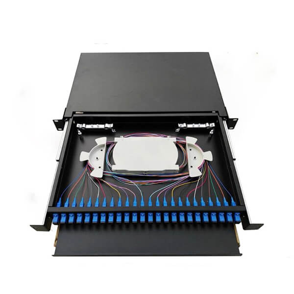
2. The optical fiber distribution frame (ODF) should be well grounded, and must be installed firmly and neatly. The optical cable stripping section to the fusion splicing tray must be protected by a hose, the optical fiber core fusion splicing tray should be placed firmly, and the core fusion point should be in the center of the heat shrinkable tube. , the fiber core disk fiber is neat without damage.
3. Optical cable junction box: After the construction of the optical cable, the inlet and outlet of the optical cable must be blocked with glue and other items. The optical cable must be fixed with steel hoops in the optical junction box; Plastic hose transition connection, the wiring should be reasonable and beautiful.
4. The optical terminal box (OTB) must be installed on a fixed object indoors, and the optical cable must be fixed with a steel hoop in the OTB; the optical fiber from the stripped end of the optical cable to the terminal box is connected with a plastic hose, which cannot be moved arbitrarily. There are lightning protection measures.
5. The pigtails of the ODF frame should be coiled neatly and properly protected according to the actual situation of the ODF frame.
6. The reinforcement core is properly grounded, and the reinforcement core needs to be connected to an independent protective ground.
7. In principle, the optical cable introduced into the machine room rack in the new optical cable project adopts the indoor optical cable whose reinforced core is non-metallic medium.
8. Optical cables should be listed at the entrance, at the corner of the cable rack, above the ODF rack and in an obvious position between the cable rack.
9. When the optical cable meets the ceiling indoors, it should be encapsulated by a plastic tube.
5. What are the requirements for direct buried laying of optical cable wiring?
1) Before laying out the optical cable, the construction and related personnel should be properly trained on the matters that should be paid attention to in the construction, such as the essentials of the laying out method and safety, and ensure that the construction personnel obey the command.
2) Check whether the specific direction of the optical cable routing, the laying method, the environmental conditions and the specific location of the joint conform to the construction drawing design.
3) Check the ground distance and the length of the relay segment.
4) Determine the specific location and treatment measures of the section where protective measures need to be taken for optical cables to pass through obstacles.
5) Determine the location, location and quantity of optical cable protection such as trenches, sills, slopes, and blockages.
6) The minimum distance between optical cables and other facilities, trees, buildings and underground pipelines must meet the acceptance technical standards.
7) The route of the optical cable, the laying position and the connection point should be safe and reliable, which is convenient for construction and maintenance.
8) Before excavating the cable trench, the construction unit shall lay the gray line along the straight line section of the gray line along the route according to the approved construction drawing design, and there shall be no serpentine bend or disconnection.
9) The direct buried optical cable shall be excavated according to the standard requirements.
10) Where trenches cannot be dug, the pipelines can be laid overhead or drilled.
11) Due to the heavier weight of the direct-buried optical cable for climbing and the complex terrain, the construction is difficult and requires a lot of labor, so enough personnel should be provided
12) The bottom of the ditch should be smooth and firm, and a part of sand, cement or support can be pre-filled if necessary.
13) When laying optical cables, engineers and technicians should be equipped with necessary communication equipment, such as walkie-talkie speakers.
14) The bending radius of the optical cable should be less than 15 times the outer diameter of the optical cable, and should not be less than 20 times during the construction process.
15) Manual or mechanical traction can be used when laying, but attention should be paid to guidance and lubrication.
16) During mechanical traction, the progress adjustment range should be 3~15m/min, the adjustment method should be stepless speed regulation, and it should have automatic stop performance. During traction, centralized traction, intermediate auxiliary traction, and decentralized traction should be selected according to factors such as traction length, terrain conditions, and traction tension.
17) After the optical cable is laid, the end of the optical cable should be treated with moisture-proof, and should not be soaked in water.
18) After the laying is completed, the soil should be covered and compacted as soon as possible.
To sum up, the optical cable must be listed in time after the construction of the optical cable, so that it can be recognized later, and the optical cable should be protected to prevent it from being damaged by man. Optical cable is an important carrier of signal transmission and is very important. Protecting the integrity of optical cable is to protect the normal operation of the entire network.