
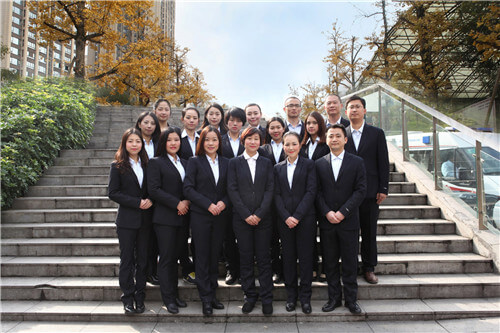
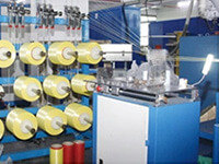
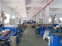
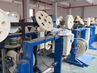
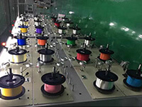
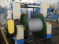
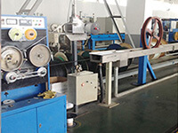
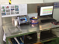
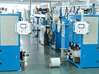
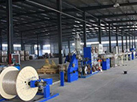
Hunan Zhongruiguang Communication Equipment Co.,Ltd.is a 10 years experienced leading manufacturer for fiber optic cables in China.The factory has 10 production lines and 30 technical innovators to solve product production needs for customers.
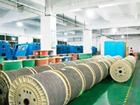
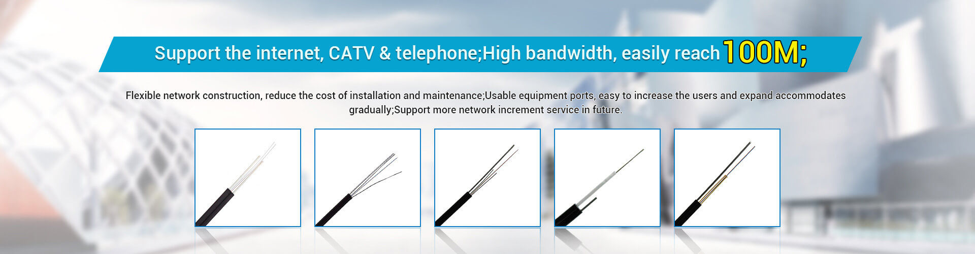
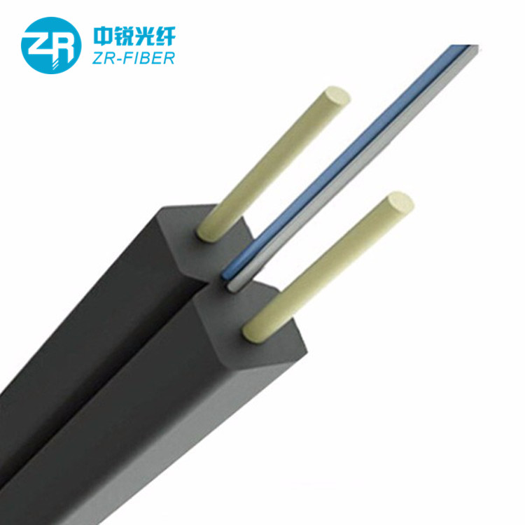
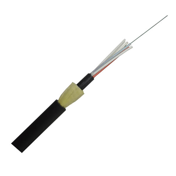
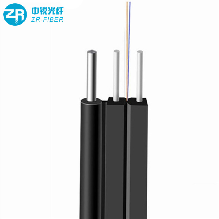
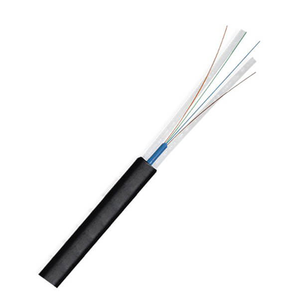
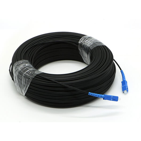
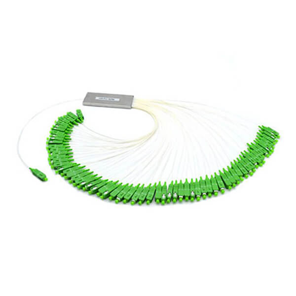
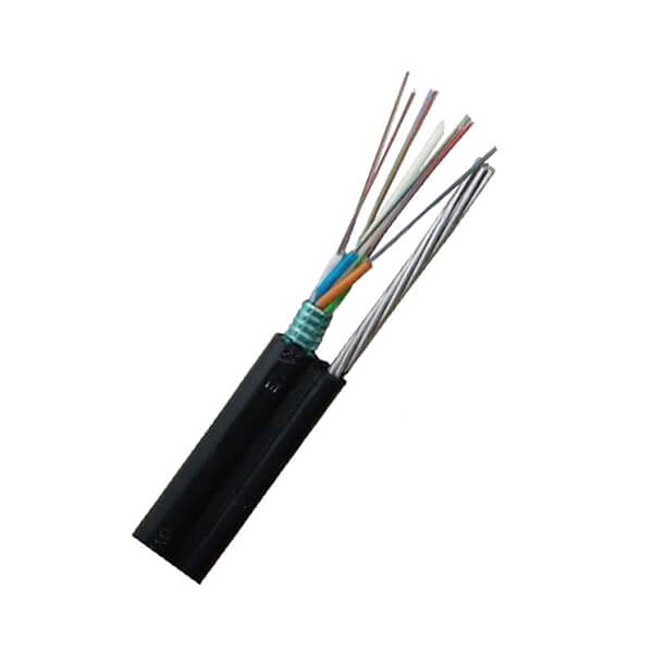
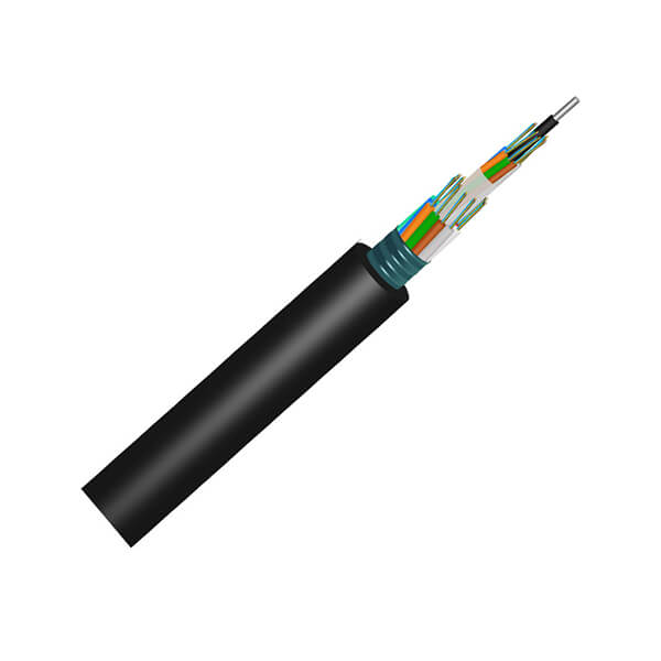
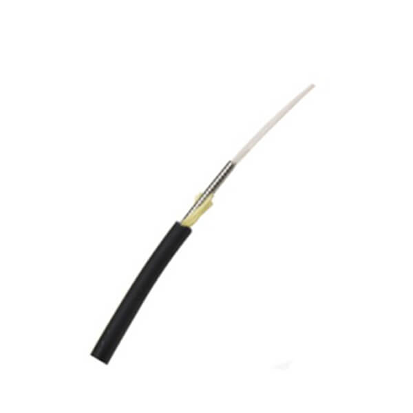
Fiber optic cable, also known as optical fiber cable, is a type of Ethernet cable which consists of one or more optic fibers that are used to transmit data. It is an assembly similar to an electrical ...
Copyright © 2005-2022 Hunan Zhongruiguang Communication Equipment Co.,Ltd. All rights reserved