
PLC (Planar Lightwave Circuit) splitter devices are used to split a single optical signal into multiple outputs. They are commonly used in fiber optic networks to distribute a signal from a single input to multiple outputs. In this article, we will discuss the function and analysis of PLC splitter devices.
Function of PLC Splitters
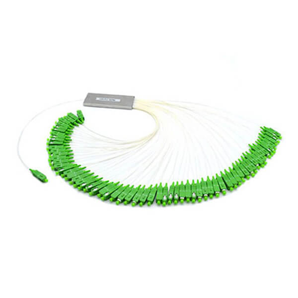
PLC splitters are used to split a single optical signal into multiple outputs. They use a planar lightwave circuit (PLC) to divide the signal into multiple paths. The PLC splitter consists of a block of optical waveguides that are fabricated onto a substrate. The waveguides are designed to split the signal equally into multiple outputs.
PLC splitters are available in various configurations, including 1x2, 1x4, 1x8, 1x16, 1x32, and 1x64. The "1x" refers to the number of inputs, and the number after the "x" refers to the number of outputs. For example, a 1x4 PLC splitter has one input and four outputs.
Analysis of PLC Splitters
PLC splitters have several characteristics that are important to consider when choosing a splitter for your fiber optic network.
Split Ratio: The split ratio refers to the ratio of the output power of each port to the input power of the splitter. For example, a 1x2 splitter with a 50/50 split ratio will split the input signal equally into two outputs. The split ratio can vary depending on the configuration of the splitter.
Insertion Loss: The insertion loss is the amount of power lost when the signal passes through the splitter. This loss is caused by the splitting of the signal and the conversion of the optical signal to an electrical signal. The insertion loss can vary depending on the configuration of the splitter and the wavelength of the signal.
Return Loss: The return loss is the amount of light reflected back to the source due to imperfections in the splitter. A high return loss can cause interference in the signal and reduce the quality of the transmission.
Polarization Dependent Loss (PDL): PDL is a measure of the difference in insertion loss for light polarized in different directions. PDL can cause a reduction in signal quality and should be minimized.
Temperature Sensitivity: PLC splitters can be sensitive to temperature changes, which can cause variations in the output power of the splitter. The temperature sensitivity can be minimized by using high-quality materials and designing the splitter to minimize thermal effects.
Applications of PLC Splitters
PLC splitters are used in various applications, including:
Passive Optical Networks (PONs): PLC splitters are used in PONs to split a single optical signal into multiple outputs to provide service to multiple subscribers.
Fiber to the Home (FTTH): PLC splitters are used in FTTH networks to distribute a signal from a single input to multiple outputs to provide service to multiple homes.
CATV: PLC splitters are used in CATV networks to distribute a signal from a single input to multiple outputs to provide service to multiple customers.
Data Centers: PLC splitters are used in data center networks to distribute a signal from a single input to multiple outputs to provide connectivity to multiple devices.
In conclusion, PLC splitters are essential components in fiber optic networks, providing the ability to distribute a signal from a single input to multiple outputs. When choosing a PLC splitter, it is important to consider the split ratio, insertion loss, return loss, PDL, temperature sensitivity, and other characteristics to ensure the best performance for your specific application.