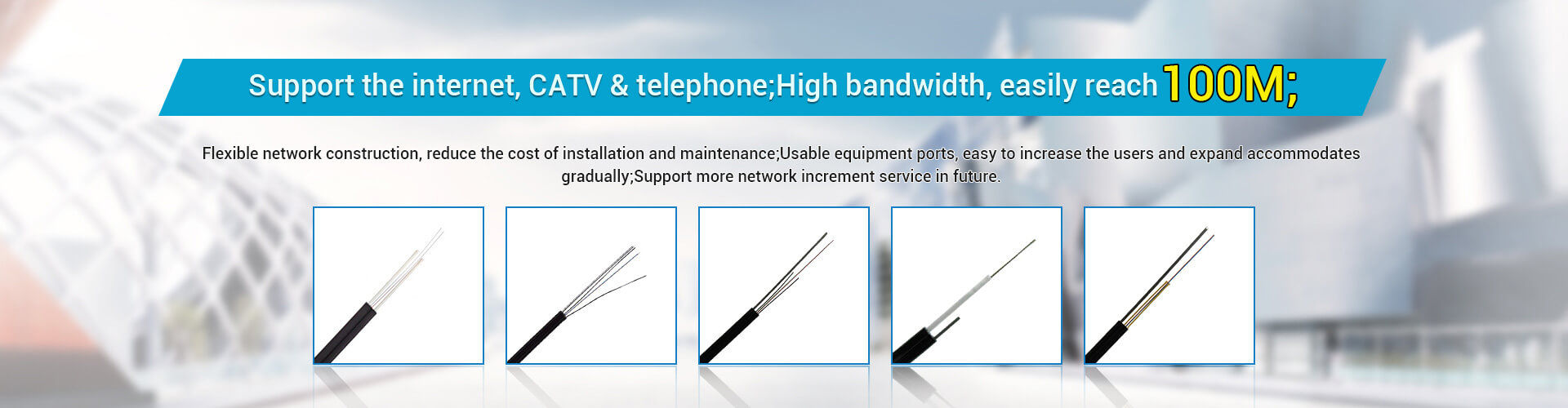

Optical fiber is an abbreviation for optical fiber, which is composed of thin glass filaments with a diameter of about 0.1 mm. It is transparent and slender, and although thinner than a human hair, it has a waveguide structure that encloses light in it and propagates it in the axial direction. Because the optical fiber medium has the following advantages: wide transmission frequency band, large communication capacity; low loss; no electromagnetic interference; thin wire diameter, light weight; The role of the information transmission core channel, that is, the vertical backbone, uses optical fibers to connect the wiring rooms on each floor to the main engine room.
Because optical fiber communication has a series of excellent characteristics, optical fiber communication technology has developed extremely rapidly in recent years. It can be said that this emerging technology is an important symbol of the new technology revolution in the world, and it is also the main transmission tool of various information networks in the future information society.
Design and Construction of Optical Fiber Backbone
1. Design of optical fiber backbone
The vertical backbone subsystem refers to the transmission medium that connects the main distribution frame (or optical fiber junction box/box) between the equipment and the vertical end distribution frame (or optical fiber junction box/box) between the wiring rooms on each floor. It is mainly composed of optical fiber and large logarithmic cable. Among them, the optical fiber is mainly responsible for the transmission of data information, and the main application protocol is the TCP/IP protocol.
1.1 Structure of Optical Fiber Backbone System
The relationship between the backbone structure of the integrated wiring system and the network architecture is very close. The network architecture is basically determined, and the structure of the wiring system can be determined. What architecture and transmission medium are used in the network will affect the design of the wiring system. Similarly, the star or tree topology of the integrated wiring system also makes the basic topology of the network a star or tree topology.
At present, for the network structure, the hierarchical star structure is mainly used, and the network is divided into two levels.
The first level is the network center, which is the central node, which arranges the core equipment of the network, such as routers, switches, servers (WWW servers, e-mail servers), and reserves external communication interfaces.
The second level is the switch in each wiring room, which is the second level node. The optical fiber backbone is set up as the data transmission trunk in the building, from the core layer to the secondary nodes, and is terminated between the distribution lines. The secondary switch can be an Ethernet or Fast Ethernet switch, which is connected up to the backbone switch in the network center and directly connected to the servers and workstations down. The network structure is shown in Figure 1:
According to the above-mentioned network structure, in the integrated wiring system, we also adopt the design of star structure. The star physical structure is the most flexible physical structure, which can form different logical structures through different adapters or network devices, which is not only suitable for the needs of the telephone system, but also suitable for the requirements of computer networks and other intelligent systems. The whole structure is roughly divided into two-level star, trunk part and horizontal part. The center of the star structure of the trunk part is in the weak current access room on the first floor, radiating to each floor, and the medium uses optical fiber and large logarithmic twisted pair. The star center of the horizontal part is in the floor wiring room, and the horizontal twisted pair is drawn from the wiring frame to each information point. The center of the star structure is the management subsystem, which realizes the connection, configuration and flexible application of the entire wiring system through the two-point management method.
For the above design principles and understanding of this project.
In addition, considering that the network system may be designed into several network segments (such as external network, office network, management network, weak power grid, etc.) that need to be physically separated according to customer requirements. Likewise, the cabling system should physically isolate the cabling depending on the application.
For modern office buildings, IP telephony is increasingly used in practical work. For the integrated wiring system, the information transmission of the IP phone will also be undertaken by the optical fiber backbone, without the need to erect the traditional large logarithmic copper cable. For some equipments (such as fax machines) that still need analog transmission, they can be converted to TCP/IP through gateway equipment.
1.2 Selection and Design of Optical Fiber Backbone Products
First, it is necessary to determine the data volume requirements in the project and thus determine the type of fiber backbone.
To determine the amount of information and bandwidth of the network, the number of information points should be calculated first according to customer needs. Assuming that at the same time, 50% of the information points are in use, and each user will occupy 20M bandwidth, then according to the number of information points, the bandwidth demand of the current information backbone between weak currents can be obtained. According to the amount of data obtained, the number of cores required to lay the optical fiber can be obtained. It is worth noting that in the design of the fiber optic trunk of the integrated wiring, the trunk system should preferably consider 100% redundant backup.
Next, confirm the fiber type and quantity:
(1) Determine the fiber type according to the fiber laying position: indoor/outdoor/indoor/outdoor/armored, etc.
(2) Determined according to the transmission distance, transmission speed, etc.: multi-mode (OM1/OM2/OM3)/single-mode.
(3) Determine according to the connector requirements: LC/SC and other fiber types.
(4) Determine the length of the optical fiber according to the wiring structure and site conditions: length = (the number of layers from the main distribution frame × layer height + the distance from the weak point well to the main distribution frame + termination tolerance) × the number of fibers required for each layer; Note: The fiber part of the termination tolerance is 10m.
(5) According to the fire protection requirements, determine whether the outer skin of the optical fiber is low-smoke and halogen-free.
1.3 Recommended products for selection
There are two main performance parameters for fiber optic cabling systems: attenuation and bandwidth. The basic performance difference between optical fiber and copper wire is that optical fiber has greater bandwidth and less attenuation than copper wire, so the transmission distance of optical fiber is longer and the transmission rate is higher.
ACS fiber series products have always focused on high quality and high performance, and each index greatly exceeds the requirements of ISO/IEC 11801, EN 50173 and TIA/EIA 568B.
ACS fiber and series products have the following salient features:
High installation efficiency;
The fiber capacity is large, and the fiber optic cable with the same number of cores has a smaller outer diameter size;
Low-smoke halogen-free outer layer material has extremely low combustion energy;
No need to add additional optical cable channels;
High-density connectors and connection panels optimize the volume and structure of the connection system;
Simple and flexible interconnection devices that can cope well with current and future applications;
Modular structure, easy to expand and extend the performance and quantity;
Different wiring structures select the applicable configuration according to the needs.
For the most mainstream 10G OM3 multimode optical cable, the 10G multimode optical fiber system of IBM ACS can not only support the functions of 10G network applications, but also fully backward compatible and support 10M, 100M, and 1G network applications, and 1G The network application exceeds 1000m, which greatly exceeds the 275m distance of the existing multimode fiber system. LaserTrans technology is the world's first multimode fiber solution to support serial transmission of 10G over 850nm wavelengths over distances in excess of 550m by eliminating the need for expensive optoelectronic equipment previously required to reach speeds of 10G in multimode fiber . In addition, IBM ACS has the following features:
It supports transmission applications up to 10Gbps and a short wavelength bandwidth of 4700MHz at 850nm.
IBM ACS multi-mode 10 Gigabit fiber 10Gbps transmission application length can be divided into three types, 10G ~ 150M, 10G ~ 300M, 10G ~ 550M, to meet the needs of different users in different occasions.
2. Design of optical fiber in data room
2.1 The structure of the optical fiber backbone system of the data room
In the building data room or data center, the TIA-942 protocol should be referred to, and the optical fiber backbone should be designed according to the structure shown in Figure 4.
Set up a main distribution area (MDA) in a data room or data center. Network equipment, servers, and fiber aggregated at the building's main distribution frame (MDF) are again aggregated into the main distribution area in the computer room or data center. Through the optical fiber jumper between the main distribution area, the jumper connection between devices is completed.
It is recommended to use relatively fixed pre-connected optical cables between the main distribution frame and the equipment cabinet, to avoid the jumper confusion caused by the direct jumper between the equipment and the frequent plugging and unplugging of the jumper on the equipment.
A high-density distribution frame can be used in the main wiring area, such as 5HU space to achieve 288-core wiring function, and the product structure adopts a modular structure. The main optical fiber adopts pre-connected optical cable, which does not require on-site termination. It is convenient for system expansion. It is only necessary to directly terminate the connector of the pre-connected optical cable, and the main trunk adopts the MPO connector. Maintenance of the engine room.
3. Construction of optical fiber backbone
Due to the importance and fragility of the optical fiber backbone, the construction should be as careful as possible. The following points should be noted:
(1) The guiding ideology of optical cable wiring in local area network: it is required to be concealed and beautiful, and at the same time, it cannot break the structure of each building, etc., and avoid power lines and other lines by using the existing space. protection of.
(2) Optical cable construction, which is specifically divided into wiring, optical fiber fusion and testing.
(3) Optical fiber wiring should be organized and completed by professional construction personnel, and the optical fiber should be straightened as much as possible during wiring.
(4) When more than 4-core optical cables are put in the pipe, the utilization rate of the pipe diameter of the straight pipe should be 50% to 60%, and the utilization rate of the pipe diameter of the curved pipe should be 40% to 50%.
(5) The bend should not be folded to less than or equal to 90° to avoid damage to the fiber core.
(6) Marks should be made at both ends of the optical fiber.
(7) Turning radius of optical fiber installation: the turning radius during installation is 10 times the outer diameter of the cable, and the turning radius when it is placed for a long time after installation is 15 times the outer diameter of the cable.
(8) A good optical fiber fusion splicer and testing instrument should be selected, and professional and experienced operators should be required to perform fine fusion splicing.
(9)After completion, the fiber link test should be done to form a document. The results of the fiber test must meet the following standards: the link loss of 1000M must be below 3.2dB; the link loss of 100M must be below 13dB.
Copyright © 2005-2022 Hunan Zhongruiguang Communication Equipment Co.,Ltd. All rights reserved