
Optical fiber is the abbreviation of optical fiber, which is composed of thin glass filaments with a diameter of about 0.1mm. It is favored by the integrated wiring of enterprise LAN because of its wide transmission frequency bandwidth, large communication capacity, and especially immunity to electromagnetic interference. According to the integrated wiring specification and the characteristics of enterprise LAN construction, this paper discusses the selection of optical fiber cabling materials and the design of wiring schemes. The experience in the process of fiber optic cable wiring is analyzed and summarized.
Fiber Optic Cabling Solutions
1. Selection of optical fibers
At present, the specifications of integrated cabling products in the market are rich and varied. The choice of optical fiber is the first problem we face. We should consider the following aspects:
1) According to the performance requirements, select the suitable fiber for the application
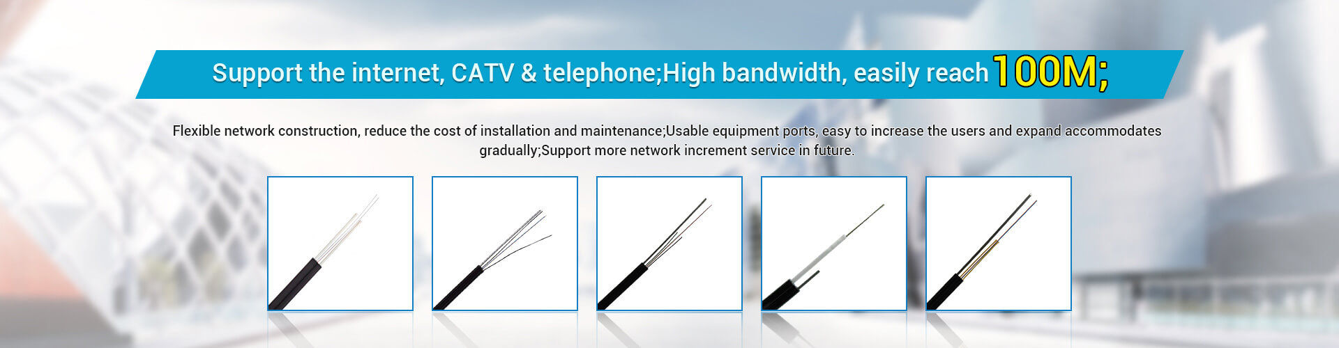
Optical fibers can be divided into single mode (SMF) and multimode (MMF) according to the transmission mode of light in them.
The core diameter of the multimode fiber is 50 or 62.5 μm, and the outer diameter of the cladding is 125 μm, which is expressed as 50/125 μm or 62.5/125 μm. The core diameter of the single-mode fiber is 8.3 μm, and the outer diameter of the cladding is 125 μm, which is expressed as 8.3/125 μm. A multimode fiber has a thicker core and can transmit light in multiple modes. However, its modal dispersion is large, which limits the frequency of transmitting digital signals, and it will become more serious with the increase of distance. Therefore, the distance of multimode fiber transmission is relatively short, generally only a few kilometers.
The central glass core of the single-mode fiber is relatively thin, the core diameter is generally 9 or 10 μm, and the outer diameter of the cladding is 125 μm, which is expressed as 8/125 μm, 9/125 μm, 10/125 μm, and can only transmit light of one mode. Therefore, its intermodal dispersion is very small, which is suitable for long-distance communication, but its chromatic dispersion plays a major role, so the single-mode fiber has higher requirements on the spectral width and stability of the light source, that is, the spectral width should be narrower and the stability should be better. .
2) Choose high quality fiber according to standard grade
Because traditional multimode fiber can only support 10 Gigabit transmission for several tens of meters, ISO/IEC 11801 has formulated a new multimode fiber standard grade, namely the OM3 category, for new optical transceivers used for 10 Gigabit applications. OM3 fiber is optimized for both LED and laser bandwidth modes and is subject to rigorous DMD testing and certification. The optical fiber cabling system using the new standard can support at least 10 Gigabit transmission to 300 meters in multimode mode, and can reach more than 10 kilometers in single mode mode (1550nm can support 40 kilometers transmission).
3) Select the most economical transmission frequency window from the perspective of cost performance
The working wavelengths of optical fibers are short-wave 850nm, long-wave 13l0nm and 1550nm. The fiber loss generally decreases with the increase of wavelength. The loss of 850nm is generally 2.5dB/km, the loss of 1.31μm is generally 0.35dB/km, and the loss of 1.55μm is generally 0.20dB/km, which is the lowest loss of optical fiber. The loss tends to increase for wavelengths above 1.65 μm. The main parameters of the 1310nm conventional single-mode fiber are determined by the International Telecommunication Union ITU-T in the G652 recommendation, and l310nm is just a low-loss window of the fiber.
Therefore, this fiber is also called G652 fiber. G.652.D is the latest index of single-mode fiber, the most stringent index among all G.652 levels, and is fully backward compatible. If only G.652 is specified, it generally means the performance specification of G.652.A, which should be paid special attention.
Optimizing applications at 850nm on multimode fibers benefits users the most, followed by applications at 1300nm on singlemode fibers.
4) In addition to the number of optical fibers and the type of optical fibers, the selection of optical fibers should also be selected according to the use environment of the optical cable.
If the transmission distance is within 2km, multi-mode fiber can be selected, and if the transmission distance exceeds 2km, relay or single-mode fiber can be selected. Optical fibers used in buildings should pay attention to their flame retardant, toxic and smoke characteristics when selecting them. Generally, the type of flame retardant but smoke can be used in the pipeline or forced ventilation; if it is in an exposed environment, the type of flame retardant, non-toxic and smoke-free should be used. When the outdoor optical cable is directly buried, the armored optical cable should be selected. When overhead, an optical fiber with a black plastic outer jacket with two or more reinforcing ribs can be used.
Based on the above analysis, regardless of single-mode or multi-mode, users should invest in the best performance at the lowest price by considering various factors from the perspective of application, transmission distance, forward-looking, and cost.
2. Laying of optical cables
Optical cables are divided into 4 cores, 6 cores, 8 cores, 12 cores, etc. according to the number of cores; they are divided into two types: overhead and direct buried according to the laying method; according to the supported distance, they are divided into multi-mode (within 2 kilometers), single-mode (2 kilometers) to dozens of kilometers). The enterprise local area network usually uses underground trenches, heating pipe trenches or buried outdoor multi-mode fibers in the park, and overhead single-mode fibers are considered in long-distance areas.
In fiber optic cabling, signal attenuation is also inevitable. There are two reasons: internal and external: the internal attenuation is related to the optical fiber material, and the external attenuation is related to the construction and installation, so it should be noted that:
1) The first thing that should be done is that the termination and maintenance of the optical fiber should be carried out by technical personnel who have received strict training, and the operation should be carried out according to the construction specifications of the optical fiber.
2)) There must be complete design and construction drawings for convenient and reliable construction and future inspection. During construction, be careful not to make the optical cable under heavy pressure or punctured by hard objects; in addition, the traction force should not exceed the maximum laying tension.
3) When the fiber is to be turned, its turning radius should be greater than 20 times the diameter of the fiber itself. When the optical fiber passes through the wall or floor, a protective plastic pipe with a mouth guard should be added, and the pipe should be filled with flame retardant filler. A certain amount of plastic pipes can also be pre-laid in the building.
4) When the optical fiber is used in the backbone network, at least 6-core optical cable should be used in the wiring room of each floor, and 12-core optical cable should be used for advanced applications. This is considered from three aspects: application, backup and expansion.
5) The most important thing for long-distance fiber laying is to choose a suitable path. The shortest path is not necessarily the best, but also pay attention to the right to use the land, the possibility of erection or burial, etc.
3. Design principles of integrated wiring system
1) Systematic cabling system
Information ports in any area of the building eliminate the need for rewiring when reconnecting or relocating workstation terminals
2) Standardization of integrated wiring system
The information ports and corresponding supporting cables of the system must be unified so as to connect all types of networks and terminals smoothly, and at the same time, the flexibility of system maintenance and reconfiguration can also be realized.
3) The advancement and continuity of the integrated wiring system
The system must remain obsolete over a long period of time and not lose manufacturer support due to advancements. (Full consideration of system development and upward compatibility)
4) High performance price ratio of integrated wiring system
The selected wiring system has a reasonable structure, and the selected raw materials, media, connectors, and electrical equipment have good physical and electrical properties, and the price is moderate.
5) Practicality of integrated wiring system
The designed system should fully meet the current needs and development needs of users.
6) The integrated wiring system is flexible and convenient
The structural design should be easy to wire, the information port should be set reasonably, and it should be plug and play.
7) Integrated wiring system can be managed
Use standard building block connectors for wiring management.
8) The integrated wiring system has good scalability
The system is designed according to standard specifications, and the structure and connectors that are easy to expand are adopted to ensure easy expansion and replacement.
3. Optical fiber terminal box installation and wiring scheme
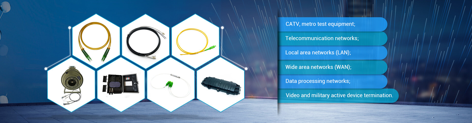
The fiber optic terminal box is a terminal connector of an optical cable. One end of it is an optical cable and the other end is a pigtail, which is equivalent to a device that splits an optical cable into a single optical fiber. The user optical cable terminal box installed on the wall, its function is to provide Fusion splicing of optical fibers and optical fibers, fusion splicing of optical fibers and pigtails, and handover of optical connectors. It also provides mechanical protection and environmental protection for the fiber and its components, and allows for proper inspection to maintain the highest standards of fiber management. The terminal box is usually installed on a 19-inch rack and can accommodate a relatively large number of fiber optic cable ends.
Common terminal boxes are: wall-mounted optical fiber terminal box, rack-mounted optical fiber distribution box, optical fiber distribution frame ODF unit (Optical Distribution Frame), optical fiber transfer box, and the specific application should be based on project scale, cost, scalability. specific consideration.
The optical cable terminal box is mainly used for the fixing of optical cable terminals, the fusion of optical cables and pigtails, and the storage and protection of residual fibers.
The optical fiber distribution frame is used for the termination and distribution of the central office trunk optical cable in the optical fiber communication system, which can easily realize the connection, distribution and scheduling of the optical fiber line.
The optical fiber topology of the enterprise is usually star-shaped. The wiring scheme will select the type of fiber-optic terminal box according to the scale and budget of the project. In the star-shaped network layout, the optical fibers are collected from each information point to the network center:
1) For the solution with a relatively small number of optical fibers and a relatively simple star layout, "network center rack-type optical fiber distribution box to rack-type optical fiber distribution box" is adopted. Increase the corresponding fiber distribution frame, poor scalability;
2) For the scheme with a large number of optical fibers and a simple star-shaped layout, "network center ODF unit to rack-type optical fiber distribution box" is adopted; the project cost is moderate, and the scalability is general;
3) For the scheme with a large number of optical fibers and a complex star-shaped layout, "the network center ODF unit to the optical fiber junction box to the rack-type optical fiber distribution box", the project cost will increase due to the use of the optical fiber junction box, and the scalability is very high. it is good.
The choice of the scheme should not only consider the cost, scalability, etc., but also consider the geographical characteristics of the network center computer room and each information point. If the network center happens to be in the center of the park, the second scheme can better meet the needs; if the network If the center is located in a corner of the park, the information points are relatively concentrated, and the network center is far away, the third solution can be considered, which is convenient for maintenance and reduces construction complexity.