
Optical fibers have become the main means of long-distance wired signal transmission, and installation and maintenance of optical fibers are also the basic skills of weak electricians. There are many theoretical knowledge, components and laying points involved in optical fiber, and we have made some sorting out here.
three lights
Not all light can be used for signal propagation in optical fibers. There are mainly three wavelengths of light used in light: 850 nm, 1300 nm, 1550 nm.
Where is it used?
The wavelength of light used by single-mode fiber is 1310 nm or 1550 nm, and the wavelength of light used by multi-mode fiber is mostly 850 nm.
The difference between single mode and multimode
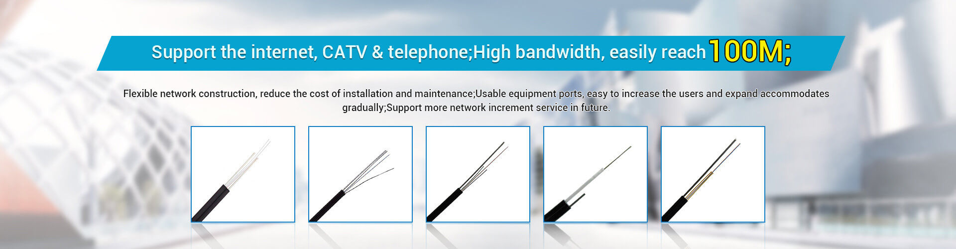
• The central glass core of multimode fiber is thicker (50 or 62.5 μm) and can transmit light in multiple modes. However, its intermodal dispersion is relatively large, which limits the frequency of transmitting digital signals, so the transmission distance of multimode fiber is relatively short, generally only a few kilometers.
• The central glass core of single-mode fiber is very thin (the core diameter is generally 9 or 10 μm), and can only transmit light of one mode. Therefore, its intermodal dispersion is very small, which is suitable for long-distance communication.
thread color
A simpler way of distinguishing is that the sheath of multimode fiber is orange, and the sheath of single mode fiber is yellow.
Dispersion and Loss
In single-mode fiber, 1310 nm light has minimal dispersion and 1550 nm light has minimal loss.
So, what exactly is the loss?
1310 nm : 0.35~0.5 dB/km
1550 nm : 0.2~0.3 dB/km
850 nm : 2.3~3.4 dB/km
There are too many enemies of light signals
Optical loss is one of the causes of optical fiber signal attenuation. In addition, scattering, absorption, etc. can also cause fiber signal attenuation.
Causes of Optical Loss
• Natural loss of light
• Insertion loss of optical components inserted in optical transmission lines
• Handset loss when fiber is connected
• Impedance mismatch in the cable causes light to reflect, this is called return loss
• Bending, extrusion, impurities and unevenness of fiber material can cause loss
fiber optic connection
• Fixed splicing, commonly known as dead splicing, generally adopts optical fiber fusion splicer, which is used for the direct head of optical cable.
• Active joints, commonly known as live joints, are connected with detachable connectors and are used for optical fiber jumpers, equipment connections, etc.
Tips for fixing joints
The installation of the fixed joint should use the secondary discharge welding method. First, preheat and discharge the fiber end face, shape the end face, remove dust and sundries, and at the same time make the fiber end face pressure uniform through preheating.
light has noise
In addition to attenuation, noise affects the transmission effect of optical fiber information. Attenuation means less useful signal, and noise means more useless signal.
cause of noise
• Extinction ratio unqualified
• Random variation of light intensity
• Caused by time jitter
• Receiver point noise and thermal noise
• Fiber Mode Noise
• Pulse broadening due to dispersion
• Modulo distribution noise of LD
• Frequency chirp of LD
• Reflection
What? And dispersion?
Dispersion is also an important factor affecting the transmission of optical signals.
Dispersion: The widening of the bandwidth caused by a light pulse traveling a distance along a fiber. It is the main factor limiting the transfer rate.
cause of dispersion
• Intermodal dispersion: Occurs only in multimode fibers because light in different modes travels along different paths.
• Material dispersion: Different wavelengths of light travel at different speeds.
• Waveguide Dispersion: Occurs because light energy travels at slightly different speeds as it travels through the core and cladding. In single-mode fiber, it is very important to change the dispersion of the fiber by changing the internal structure of the fiber.
Effect of Fiber Material on Propagation
• Glass fiber: both the core and the cladding are glass, with low loss, long transmission distance and high cost;
• Silicone optical fiber: the core is glass, the cladding is plastic, the characteristics are similar to those of glass fiber, and the cost is lower;
• Plastic optical fiber: Both the core and the cladding are plastic, with high loss, short transmission distance and low price. It is mostly used for home appliances, audio, and short-distance image transmission.
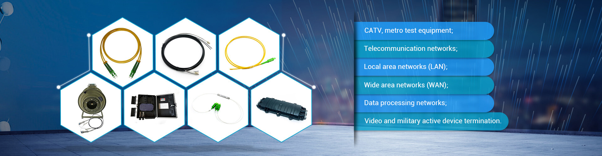
Optical module
Optical modules are components that realize the conversion of optical signals and electrical signals. Common ones include GBIC, SFP, SFP+, XFP, SFF, CFP, etc.
GBIC vs SFP
The size of the GBIC optical module is too large, occupying too much space in the switch, so that more interfaces cannot be provided on the panel of the switch. Therefore, in recent years, GBIC optical modules have been gradually replaced by SFP optical modules.
Optical interface
The optical interface is the physical interface used to connect the optical fiber cable. Usually there are several types such as SC, ST, FC.
FC type fiber optic connector/jumper
Commonly known as the round head, its external reinforcement method is a metal sleeve, and the fastening method is a turnbuckle, which is generally used on the ODF side. The FC connector is generally used in telecommunication networks. There is a nut screwed onto the adapter. The advantage is that it is reliable and dust-proof. The disadvantage is that the installation time is slightly longer.
ST-type fiber optic connector/jumper
It is usually used for multi-mode device connection. After the ST head is inserted, it is fixed by a bayonet half-circle. The disadvantage is that it is easy to break.
SC type fiber connector/jumper
Commonly known as square head and generous, the optical interface on the side of the transmission equipment generally uses the SC connector, and the SC connector is directly plugged and unplugged, which is very convenient to use, but the disadvantage is that it is easy to fall out.
LC type fiber optic connector/jumper
Commonly known as square head, small square, special interface of SFP module, it is much smaller than the above interfaces, and the same area on the switch can accommodate more ports, and the equipment of Sundray technology uses this connector.
simple summary
• FC-type fiber optic connectors are most commonly used on patch panels
• SC-type fiber optic connectors are most used in router switches
• ST-type fiber optic connectors, usually for 10Base-F connections, also commonly used in fiber optic distribution frames
• LC-type fiber optic connectors are commonly used in routers
Finally, take a look at the installation steps of the fiber
• Measure the length, strip the cable, and remove the cable jacket.
• Clean and remove petroleum filling paste from fiber optic cables.
• Bundle the fibers.
• Check the number of fiber cores, check the fiber number, and check whether the color code of the fiber is correct.
• Reinforcement core continues.
• Various auxiliary wire pairs, including business wire pairs, control wire pairs, shielded ground wire, etc. are connected.
• Fiber splices.
• Fiber splice protection treatment.
• Inventory processing of fiber residual fibers.
• Complete the splicing of the cable jacket.
• Protection of fiber optic connectors.