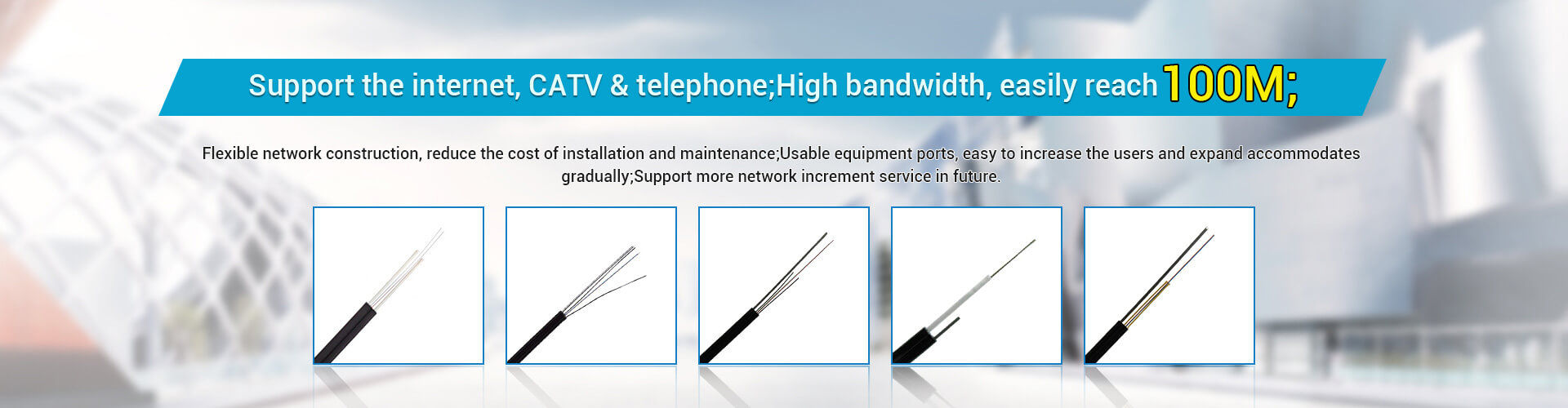
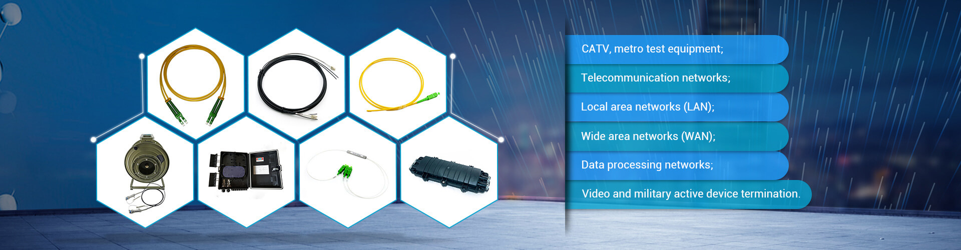

Integrated wiring is an emerging discipline, it is integrated with communication, computer network technology, information of the intelligent building and complex foundation, it can support voice, computer networks, security alarm, public broadcasting and stage and video, entrance guard, intercom, IC card, building equipment monitor system, and many other transport needs of the system, It also provides a flexible and convenient solution and a unified physical network platform for the signal transmission of these systems. It brings flexibility and convenience to users and also brings good economic benefits.
With the rapid development of communication technology, information network has gradually become an indispensable part of people's life, and integrated wiring is the foundation of information network realization, is the powerful support of present and future communication systems. Cabling provides high-performance solutions for network applications, avoids the repeated waste of hardware resources, and gives full play to the advantages of cabling.
For the work before the opening of the information network, the key is to ensure the quality of wiring during the construction. This is a prerequisite for the healthy running of the network. However, the network management personnel of many owners may pay more attention to the devices running the network and do not directly participate in the cabling phase. Most units will wiring to infrastructure projects, so easy to cause problems on the work of connection.
For wiring, wiring product manufacturers usually provide 15 to 20 years of quality assurance, and the premise of quality assurance needs to do two points, one is the project needs to be certified by the manufacturer of engineers to participate in the design, construction; The second is that each link must be authenticated and tested according to international and domestic standards, and each link must have a test report. So the quality that ensures wiring basically depends on the construction quality of wiring system.
Construction of integrated wiring
1. The main steps of comprehensive cabling construction
The main steps of cabling construction are:
(1) Site investigation, including route routing, should consider the concealment and damage to the building (structural characteristics of the building), avoid power lines and other lines while using the existing space, and carry out necessary and effective protection requirements for cables to ensure the workload and feasibility of construction.

(2) Planning, design and budget, determine the route according to the above situation and apply for approval. In case of drilling and slotting in important bearing positions of the building, it is necessary to apply to the project management department, otherwise it violates the construction regulations. The whole construction scheme and the description of the damage degree shall be approved by Party A and the management department. On the basis of the planning with the formal final permit procedure, the materials and labor shall be calculated, and the cost of the management operation in the design implementation shall be considered comprehensively, and the budget, construction period and the arrangement of the construction scheme shall be put forward.
(3) To designate project personnel and project supervisors, to be responsible for planning matters such as material preparation, work preparation and user's cooperation requirements, to put forward the cooperation schedule of various departments, and to be responsible for the construction organization and management of internal and external coordination.
(4) On-site construction, on-the-job test and spot inspection, and wiring marking system shall be made. The wiring marking system shall follow the Reference Guide for Labeling and Marking of Commercial Building Telecommunication Infrastructure, and the marking shall have a service life of more than ten years.
(5) On-site certification test, and make test report.
(6) Acceptance, making archive files, in the above links must establish a sound document, as a part of the archive files.
2 Laying cables
In the comprehensive cabling system, most of the cabling and embedded pipelines are completed at the same time as the civil construction, and cables are laid to each room through the embedded pipelines and grooves. If the fault caused by the cable is found only after the construction is completed or the network is running, the cost of repairing the fault will be very huge, and even affect the duration and delivery of the whole project. So the best way is to deal with the cable fault in the construction. To ensure construction quality, you must use a cable tester to test cables during construction. By testing the basic installation status and performance indicators of cables, you can discover existing and potential faults in links in a timely manner.
2.1 Common Cable Faults
According to statistics, about 50% to 70% of network faults are caused by cables. This is mainly related to the quality of cables and installation quality, both of which directly affect network reliability. Therefore, when purchasing products in the project, we must choose products with reliable quality and complete certification. At the same time, we should pay attention to the normative operation of construction during construction.
There are many kinds of network cable faults, which are generally divided into connection faults and electrical faults. The connection fault is caused by the construction process or the accidental damage of the network cable, such as wiring error, short circuit, open circuit, etc. The fault of electrical characteristics is that the cable does not meet the design requirements in the process of signal transmission. In addition to the quality of the cable itself, the electrical characteristics are also affected by excessive bending of the cable during construction, too tight binding of the cable, excessive stretching, and proximity to interference sources.
2.2 Test standards and parameters
General wiring test is divided into verification test, authentication test and authentication test according to the difficulty of testing, and the authentication test is divided into component level test, link level test and application level test according to the strictness of test parameters. According to the test object, engineering process and test purpose, wiring test can be divided into selection test, on-site test, supervision test/on-the-job test, acceptance test/third party test, diagnostic test, maintenance test and so on. The test standard is usually TIA 568B standard, ISO/IEC 11801-2002 standard. The standard comprehensively includes the content and method of field test for cable wiring and the requirements for test instruments. The main contents of the test include the following parameters:
(1) Line diagram/sequence diagram
A wiring diagram is a basic check to verify that a pair of wires is properly connected. Wiring errors such as open circuit, short circuit, reverse connection/crossover, straddle connection/wrong pair and crosstalk may occur during wiring construction due to terminal skills and technical errors in laying out and threading. When these errors occur, they can be easily detected by normal test equipment, and the testing techniques are very simple.
(2) length
This check mainly measures the PHYSICAL length OF THE link. The measuring instrument usually uses TDR(time domain reflectometry) test technique to measure the cable length. However, it should be noted that since the accuracy of TDR is difficult to reach 2% and the value of NVP(rated transmission rate) is not easy to be accurately measured, it is usually adopted to ignore the influence of NVP and add 10% margin to the measured length. The limit length varies slightly according to the selected test model, so it will not be restated here.
(3) the attenuation
Attenuation has been defined as insertion loss in TIA 568B. As the signal travels through the cable, the transmitted signal decreases (attenuation) due to various "resistance" encountered, and the energy lost as the signal travels along the cable is called attenuation. The attenuation of a link is the sum of the attenuation of cables and wiring components (connectors, etc.) (total insertion loss). In general, the longer the cable, the more attenuation the link will be. When the signal attenuation to a certain extent, the strength will become very weak, which will cause the link transmission information is not reliable.
(4) Proximal crosstalk
It mainly detects the noise of signal interference from one pair to another pair of twisted-pair links. This parameter is the most important parameter that decides link to transmit ability, can increase as the increase of transmission rate and increase, the isolation such as a lot of factors such as the end that connects with the direction of wiring, line, interference source is concerned, its unit is decibel (dB), basically express the ratio of transmission signal and crosstalk, absolute value is larger, crosstalk is lower.
2.3 Common mistakes in line play
Common errors include open circuit, short circuit, reverse connection, and string winding. Generally, the insulation layer fails to be punctured during crimping, resulting in the failure of the copper cable conductor to contact the IDC terminal of the module, and a good path is not formed. A short circuit occurs when a cable forms a loop that causes an error.
The case of reverse connection is more complicated. One kind of error is that two wires in a pair cross. For example, 1 corresponds to 2, and 2 corresponds to 1. Another type of error is the bonding, where 1 and 2 on one end correspond to 3 and 6 on the other. There are two reasons for this error: one end of the cable uses T 568A standard, while the other end of the cable uses T 568B standard; Second, in the practical application of the network, sometimes need to use jumper (also called crossover).
The direct connection between devices at the same layer (network protocol) requires the use of jumper cables. For example, PC to PC, hub to hub, switch to switch, and router to router need to be connected.
Since most network devices such as switches and routers can recognize the peer device intelligently, they can automatically switch the wiring to the other side. The last type of error is string winding, which is usually caused by a pair of 1 and 2, a pair of 3 and 4, a pair of 5 and 6 and a pair of 7 and 8.
For network communication, use 1, 2 and 3, 6 instead of 3, 4. Such faulty connections cannot be detected by eye or multimeter because the end-to-end connectivity is normal. The biggest danger of this miswiring is that it can cause a lot of near-end crosstalk.
This connection does not cause network failure, but makes the network run slowly, sometimes on and off, and cannot reach the speed specified by the protocol. These are soft faults, which are troublesome to check when the network is running.
3 Wiring construction should pay attention to the problem
(1) When there are excess cables at the two terminals of the cable, they should be cut off according to the required length, rather than rolled up and tied up.
(2) The distance of the anti-wound cable segment at the cable connector should not exceed 2cm. Too long will cause large near-end crosstalk.
(3) At the joint, the outer protective layer of the cable needs to be pressed in the joint but not outside the joint. Because when the cable is pulled by the outside, the stress part should be borne by the whole cable, otherwise the stress is the metal part of the cable and the joint.
(4) In the construction of cable wiring, the tension of the cable is limited, generally about 9kg, which needs to be confirmed with the cable supplier. Excessive tension damages the twisted cable, which degrades the cable performance.
4 6 Wiring construction should pay attention to the problem
(1) Because the 6 class copper conductor is usually thicker than the 5 class wire, and some manufacturers due to technical reasons to increase the cross skeleton in the online alignment, to ensure that the performance indicators stipulated in the 6 class wire standard, so the outer diameter of the 6 class cable is thicker than the general 5 class wire. In order to avoid the winding of cables (especially at the elbow), it is necessary to pay attention to the filling degree of pipe diameter when designing pipelines. According to the GB 50311-2007 standard, the pipe diameter and section utilization rate of the cable laid in the pipe and groove should be chosen differently according to different types of cables. When a large logarithmic cable or more than 4 cores of optical cable is inserted into the pipe, the pipe diameter utilization rate of the straight pipe should be 50% to 60%, and the pipe diameter utilization rate of the curved pipe should be 40% to 50%. When 4 pairs of twisted-pair cables or 4 fiber cables are put in the tube, the cross section utilization rate should be 25%-30%. The utilization rate of the section in the cable slot should be 30% to 50%. Usually 20mm diameter of the line inside the tube put two 6 type of non-shielded wire is appropriate.
(2) The bridge is reasonably designed to ensure the appropriate bending radius of cables. When bypassing other cable troughs, ensure that the slope of the bend is gentle. Consider whether the cables at both ends can be sagging to cover the cover without pressing the cables.
(3) 6 class mainly pay attention to the tension control in the process of installation, for cables with reel packaging, recommend two head at least all the arrangement is a worker, the scroll set on homemade anchor pole, pull pay-off the workers from the scroll in the first part of the cable, for partners at the other end of the line extraction, pull line cannot too much, avoid multiple thread around the ground tangles.
(4) After the wire pulling process, the redundant cables left at both ends should be sorted out and protected, and the coils should follow the original rotation direction when winding, and the diameter of the coils should not be too small. They should be fixed in the bridge, ceiling or carton, and marked well.
5 conclusion
The construction of cabling system should be combined with the actual situation to choose a reasonable scheme. First of all, the object should have a relatively accurate prediction of 15 years of user needs and environmental interference. At the same time, the other contents of the intelligent building should be investigated and studied, and the categories of the integrated wiring system should be selected to adapt to the relevant communication systems.
In the construction process of comprehensive wiring, cable tester must be used in time to do a good job of cable testing, found problems at any time to correct, to ensure the correctness of each connection completed, for the project qualified acceptance to lay a good foundation.