
With the upcoming 5G era, the role of fiber optic cables in data centers is becoming more and more obvious. Therefore, it has become an urgent problem for everyone to master the detection method of the fault point of dedicated fiber optic jumpers in data centers. Today, I will explain to you how to find and judge the fault point of optical fiber.
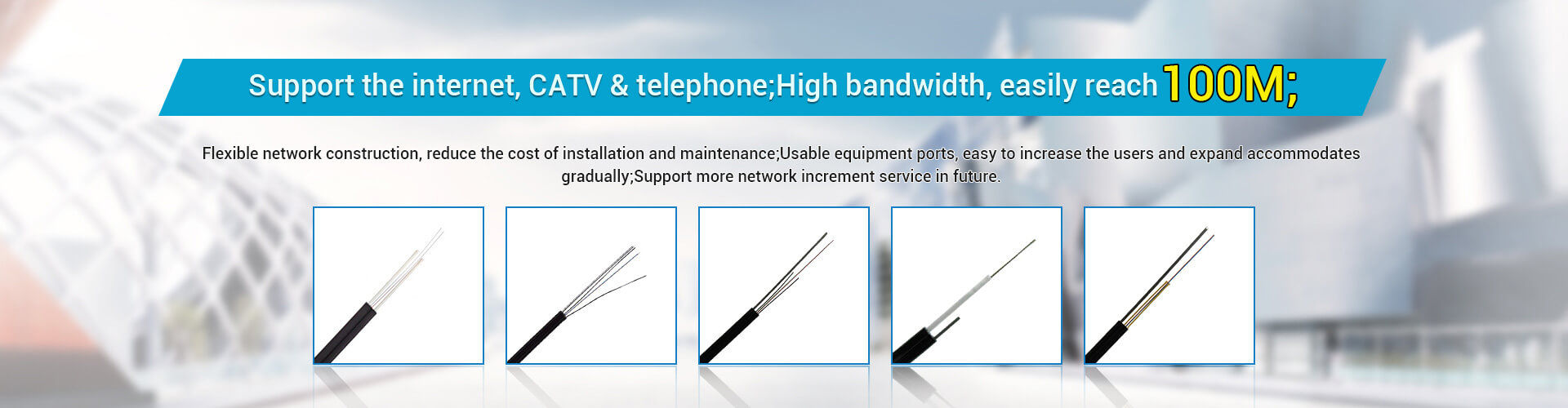
Carrier-grade single-mode single-core fiber optic cable
In the maintenance of daily optical cables, there are obstacles, and the following process is usually used to find and judge.
1. Check whether the indicator light of the photoelectric converter is normal
If the optical port (FDX) indicator of the photoelectric converter is not on. If the optical port (FDX) indicator of the A transceiver is on as B, the optical port (FDX) indicator of the transceiver is not on, and the fault is on the A transceiver side; the cause of the fault may be: A transceiver (TX) light The transmit port is broken because the optical port (RX) of the B transceiver is not receiving an optical signal.
2. Determine whether the optical fiber pigtail of the optical cable is faulty
(1) Switch detection of optical cable and optical fiber jumper: use a red light pen to send red light to one end of the optical fiber connector or coupler to see if there is a red light at the other end. The red light indicates that the optical cable or optical fiber jumper is not broken. Flange or pigtail cutout damage due to external physical factors or equipment vibration. This type of failure is accomplished by replacing the flange or pigtail.

(2) Use an optical power meter at both ends of the fiber pigtail to measure whether there is a reading to determine whether the fiber optic cable or fiber jumper is broken. Also, be sure to use alcohol to clean pigtail connection points, flanges, and device ports.
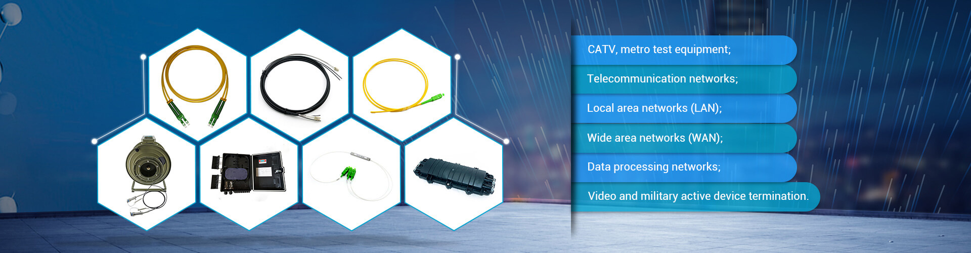
Carrier-grade single-mode single-core fiber optic cable application scenarios
3. Use OTDR (Optical Time Domain Reflectometer) test
(1) During the test, if the display has no curve, the fault point of the optical fiber is located in the blind area of the instrument, including the fiber optic cable and the pigtail connector and flange at the end of the optical cable. Pigtails of dedicated fiber optic patch cords for data centers can be added to reduce dead zone coverage. Fiber breakpoints.
(2) The remote position of the reflection curve on the screen does not match the actual length of the optical cable. There is an important "step" in the curve. If it is a splice, it means that the connector is defective or the bend radius of the fiber in the connector box is too small. Or pinched; if it's not the splice here, the fiber optic cable is pinched or sharpened here.
(3) The curve shows a strong Fresnel reflection peak at the far end, indicating that the fiber end face is perpendicular to the fiber, indicating that the end point is the end point rather than the break point, and the fault point can be on the terminal joint (flange or ODF frame).
(4) There is no reflection peak at the end of the curve, indicating that the end face is the cut surface of the optical fiber, which is most likely the destruction of the melting point between the optical cable and the pigtail. The curve shows no reflection peak at the far end, but there is a prominent curve indicating that the fiber has broken, creating a loss, and checking the melting point of the cable and pigtail.
(5)The curve shows high loss areas and high loss points. The slope of the curve becomes significantly larger, indicating that the quality of the dedicated fiber optic patch cord for the data center is not good and the attenuation is large. If the high decay point is the same as the joint, it means that the joint has lost a lot and can be re-fused. The fiber optic cable may also be deformed by force, resulting in the loss of the fiber due to the external force.